Application of Pneumatic System Pdf
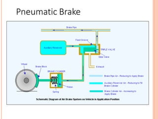
Air brakes are perhaps the most common application people think of when it comes to pneumatic technology. Modify pneumatic compressors valves tanks or cylinders Safety Concern Robot will not pass inspection of these components have been.
Basics Of Pneumatics And Pneumatic Systems Ispatguru
Hydraulic and Pneumatic Systems Topic 100 Hydraulic Systems 200 Pneumatic Systems Overview In automotive and construction equipment the terms hydraulic and pneumatic describe a method of transmitting power from one place to another through the use of a liquid or a gas.

. Read thew FIRST technical manual carefully There are many rules limitations for pneumatic systems Max working pressure is 60 Psi Max Tank storage pressure is 120 Psi Dont. A pneumatic system is a connection of various components such as compressors intercoolers controllers and actuators that converts the pressure energy of compressed air into mechanical work. Pneumatic equipment is inherently proportional but can provide two-position control when required.
Certain physical laws or principles apply to all liquids and gases. View Applications of Pneumatic Systems in Aircraftpdf from VER ERF at Gujranwala Medical College Gujranwala. A pneumatic system is a system that uses compressed air to transmit and control energy.
As the air pressure increases the compressed air begins to push. Essays Engineering Print Disclaimer. Experimental results show that the mathematical expression of the system is.
View Applications of pneumatic systems class ex w6pdf from ELECTRICAL 470 at Fiji National University. Buses trucks and train cars all stop when the pressure level changes inside of a closed air circuit. 1 kPa is equal to 001 bar or 0145 psi.
Many control sequences and combinations are possible with relatively simple equipment. System in bars bar in the metric system and in pounds per square inch psi in the English system. This system has the cost benefit and flexibility of a pneumatic system but with the precise and steady motion of hydraulics.
This work has been submitted by a student. Pneumatic controls differ from other control systems in several ways with some distinct advantages. A Automobile production lines b Pneumatic system of an automatic machine Fig.
The speed is controlled by a one way variable restrictor on each port. This work is produced in the form of linear or rotary motion. While you wont normally see consumer-grade pneumatic equipment in this field advances that have occurred due to research.
1 psi is equal to 6895 kPa or 0069 bar. 1 Common pneumatic systems used in the industrial sector. Find Forms for Your Industry in Minutes.
Automatic control system is established by PLC technology which is feasible and effective in practical application. 12 from a given system diagram read interpret and explain the operation of either a pneumatic or hydraulic multi-actuator sequential system that uses a minimum of four actuators 13 produce a suitable circuit design drawing for either a pneumatic or hydraulic reversible rotary actuation system that includes speed control in both directions. The pressure of a liquid can be measured by using a pressure gauge or manometer.
Pneumatic Systems Cha 5 Valves for Pneumatic Cylinders Cha 10 Pneumatic System Design Considerations Cha 13 Application Stories Cha 7 Pneumatic Fittings Cha 1 Why Use Pneumatics Chapter 6 Chapter 2 Pneumatic Circuit Symbols Explained Before we get any further with specifics on pneumatic system components lets take a look at the symbols used. Applications of pneumatic systems Class Exercise Week 6 In this section we will study the. Pneumatic Application Guide Do.
Pneumatic and Hydraulic Machine tools Hydraulic Hydraulic power is usually used for precise control of large forces eg. The valves that are used to control the pressure direction and flow rate of compressed air are called pneumatic valves. Examples can be found in industrial manufacturing a home garage or a dentist office.
Pneumatic systems rely on the force of compressed air to transmit power and can be found in countless applications such as power tools for diesel engines. The compressed air or pressurized gas is usually filtered and dried to. Operation of a basic hydraulic circuit.
WORKED EXAMPLE No1 A double acting hydraulic cylinder has a bore of 100 mm. Rapid assembly of electrical components in a switch box. Measured in kilopascals kPa in the SI.
Ad State-specific Legal Forms Form Packages for Equipment and Supplies. Pneumatic equipment is suitable where explosion. Pneumatic power is used for rapid but light forces eg.
Rudder control on an aeroplane. Pneumatic and Hydraulic Robots. Pneumatic systems are used where human strength and accuracy are not enough.
Low and the cylinders are often pneumatic cylinders. Pneumatic systems are used in controlling train doors automatic production lines mechanical clamps etc Fig. Streamlined Document Workflows for Any Industry.
A pneumatic system is a collection of interconnected components using compressed air to do work for automated equipment.

Combining Components In Pneumatic Systems Designs

Applications Of Pneumatic System With Machines

Pneumatic Hydraulic Pressure Sensors The Design Engineer S Guide Avnet Abacus

Basic Information On Pneumatic Systems E Pneumatic Blog
Basics Of Pneumatics And Pneumatic Systems Ispatguru

Pneumatic System Construction Working Differences Its Applications
0 Response to "Application of Pneumatic System Pdf"
Post a Comment